1C Setup the Printer
Some assembly is required to setup your Printer.
- Install the clear top cover aligning the pins with the holes on the top section of the Printer. Install one side and then bend the cover gently to allow the second pin to reach the hole on the opposite side.
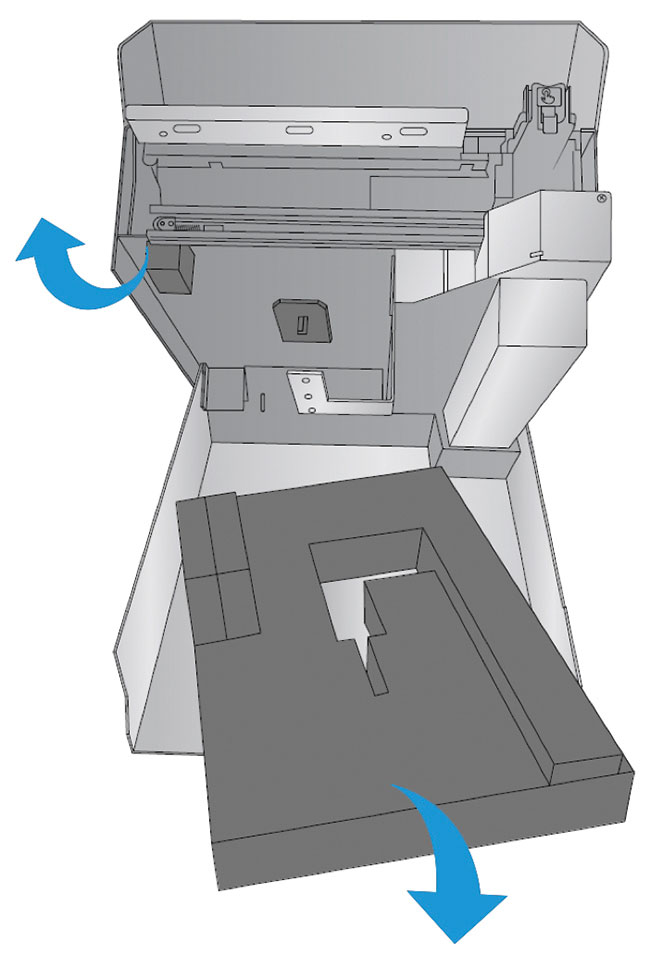
- Open the top of the Printer and remove the foam shipping insert. Keep it along with the other boxing material.
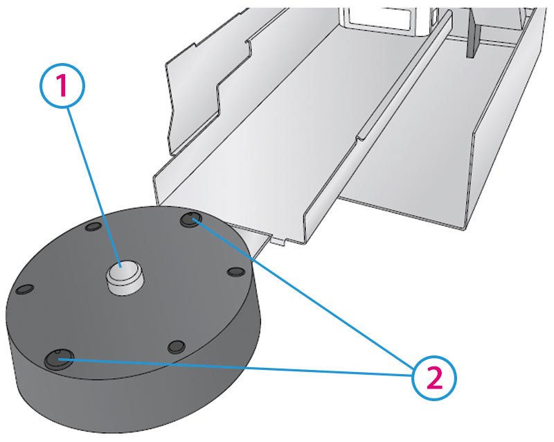
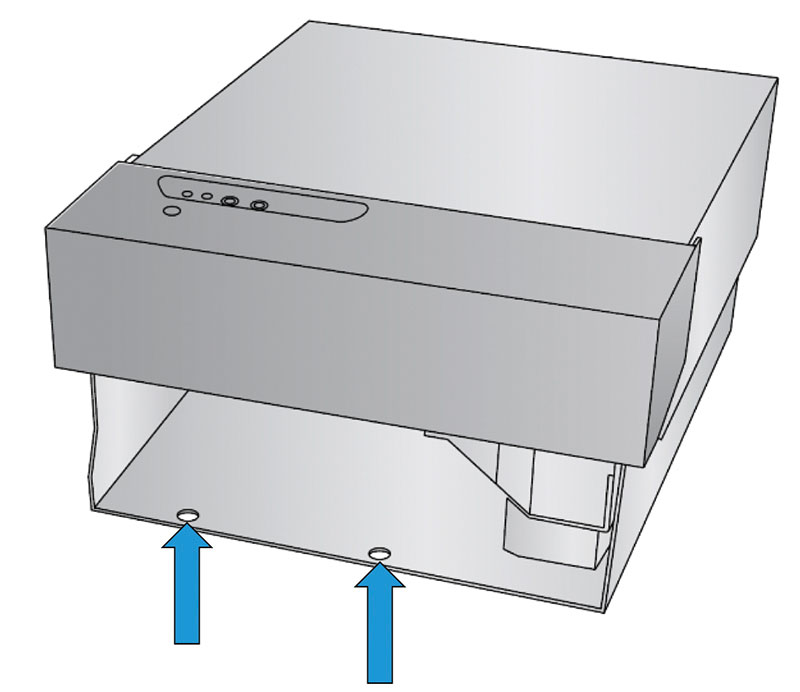
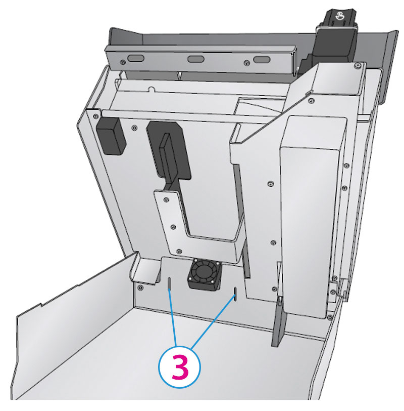
- Locate the Carousel positioning holes in the base.
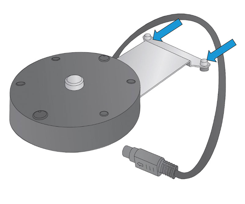
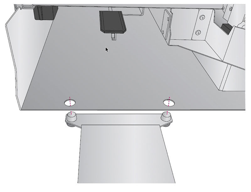
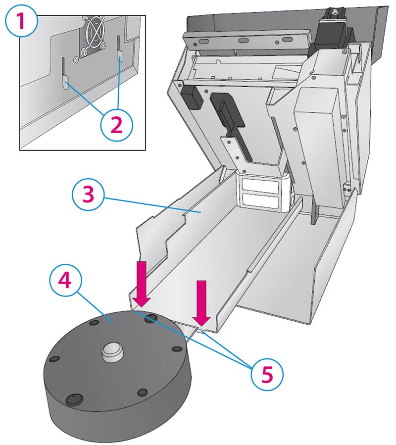
- Locate the Carousel Base. Locate the position pins.
- Lift the base of the Printer slightly and slide the Carousel Base underneath. Align the holes with the pins and lower the Printer into place.
- Locate the 8 Pin Mini Din Cable attached to the Carousel Base. Route the cable along the left side of the unit until it reaches the back of the Printer. Open the Top Cover.
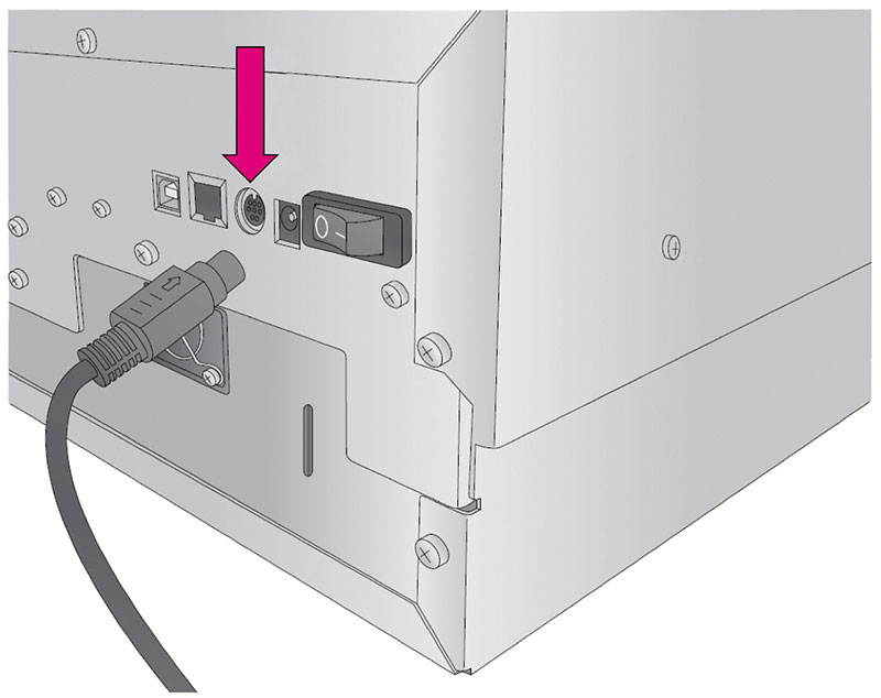
- Connect the 8 Pin Mini Din Cable to the round port on the back of the Printer.
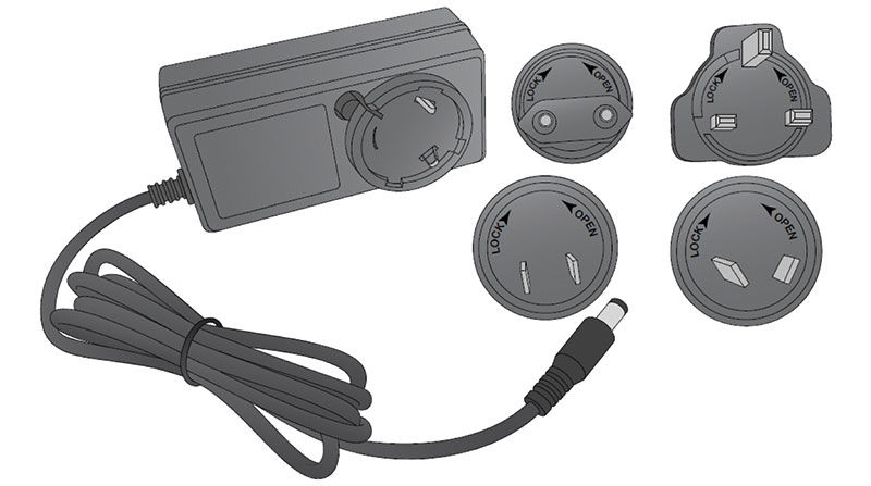
- Locate the Power Supply.
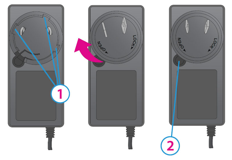
- Install the appropriate adapter by aligning the tabs on the plug to the slots in the power adapter. Rotate the plug until it snaps into place.
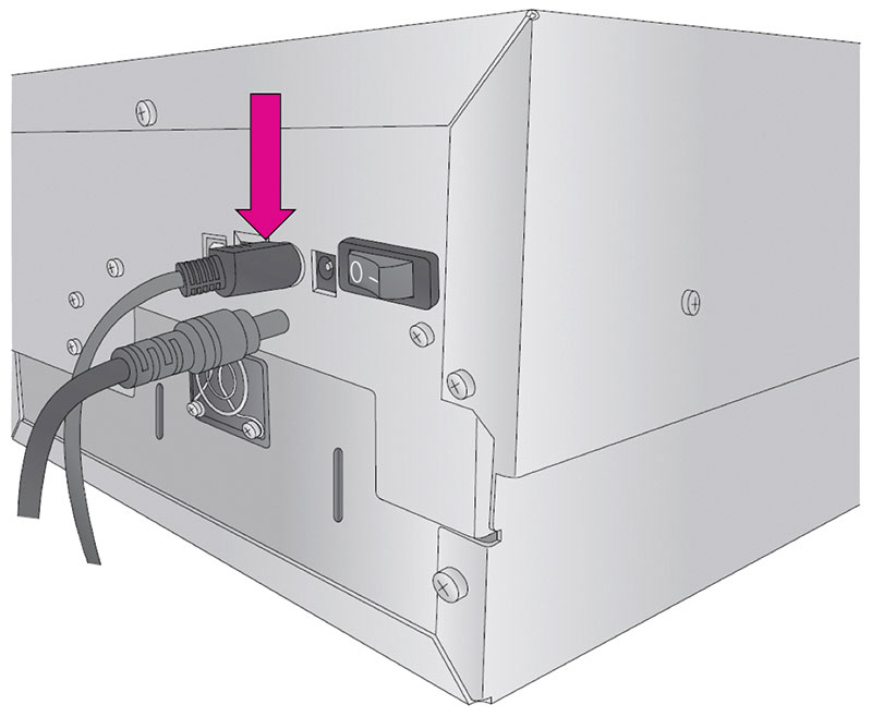
- Connect the Power Brick to a wall outlet and the round barrel connector to the back of the Printer.
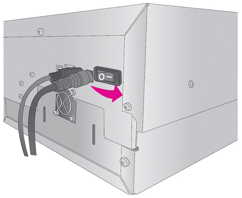
- Switch on the Power Switch.
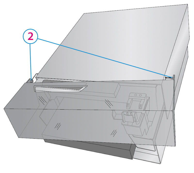
- Lift up on the top section of the Printer just under the control panel.
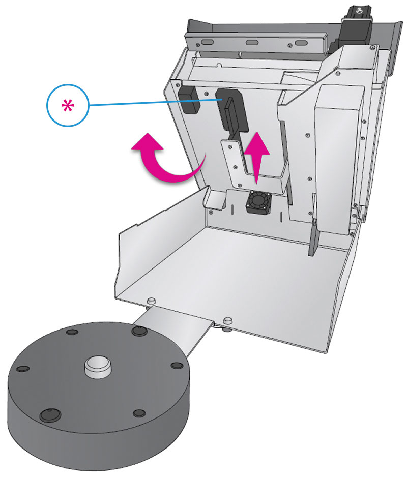
- The top section of the Printer will open and stay open with a gas spring. As long as the power is on, the cookie platform will move up and out of the way, so you may install the Crumb Catcher.
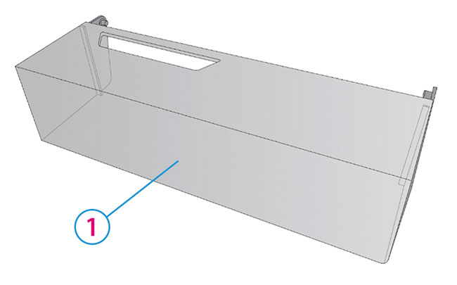
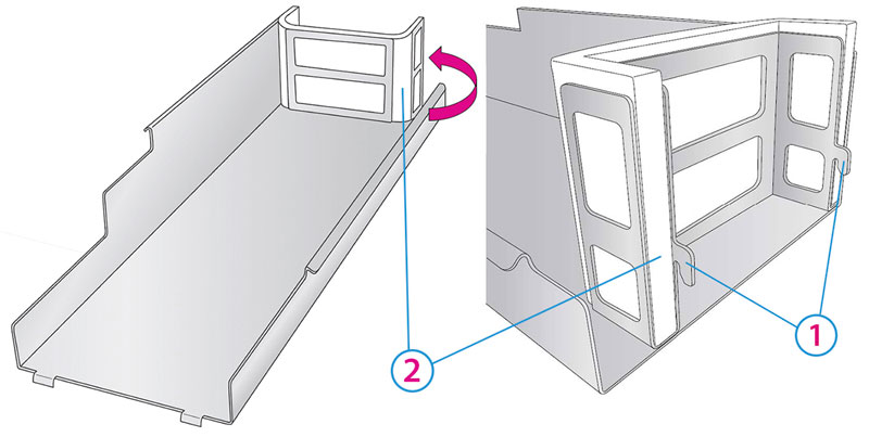
- Locate the Crumb Catcher. There are hooks on the back that correspond to slots on the back of the Printer.
- Install the Crumb Catcher by inserting the hooks into the slots. You will see the hooks through the slots on the back of the Printer. Align the front Crumb Catcher tabs on either side of the Carousel Base connection bracket.
- Lower the Top Section of the Printer.
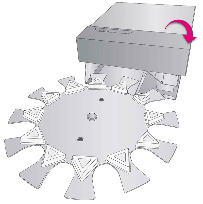
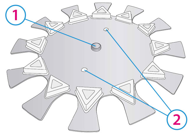
- Locate the Carousel Platter. Note the location of the alignment holes and the Center hole.
- Install the platter by aligning the center hole with the center Hub on the Carousel platter base. Rotate the platter by hand until the holes in the platter are aligned with the pegs on the base.
- Lower the Top Cover
1Clear Cover
2Pins
1Cover Open
2Route Cable Here
38 Pin Mini Din Cable
4Carousel Base
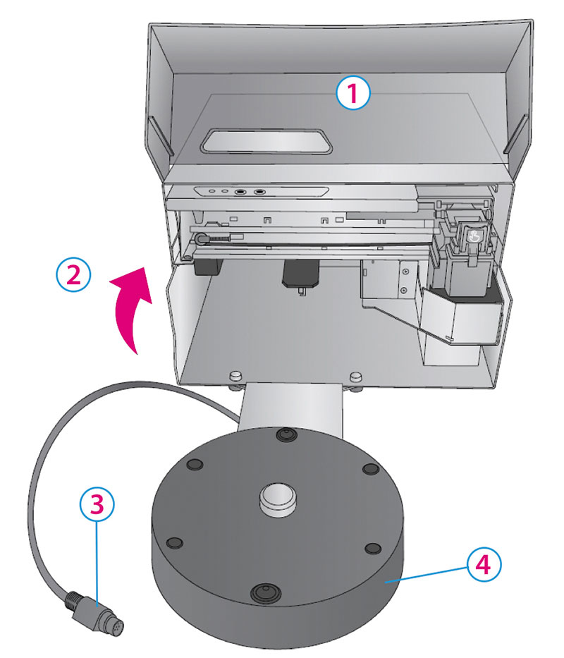
Cable Specifications:
Serial RS-232 Mini DIN8
1Slots
2Release Tab
1Lift Here
2Control Panel
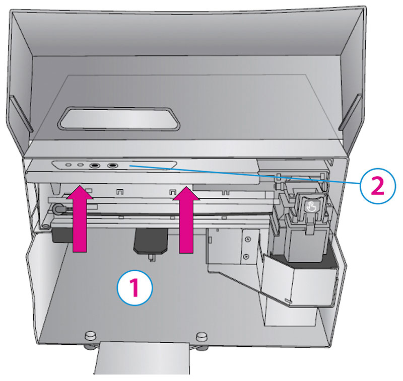
*Cookie Platform
1Hooks
2Ink Filter - Do not discard!
3Slots
1Back View
2Hooks
3Crumb Catcher
4Carousel Base
5Tabs
1Center Hole
2Alignment Holes
1Center Hub
2Alignment Pegs